

Mechanism Analysis Of The Effect Of Forging And Machining Manufacturing Processes On The Characteristics Of Gear Teeth On Their Performance
The loading of the P gear takes place on the inner and outer tooth surfaces simultaneously. Notably, this belongs to the gear parts with a more complex structure. In this case, experts apply the industrial cutting process to achieve precision. This kind of process cycle is lengthy and costly. After continuous improvement, the temperature and cold precision forging composite near-net forming of the inner and outer teeth of the P gear has been realized.
In this case, there is no need for subsequent cutting and processing to reshape the tooth. Subsequently, the problem of serious waste of cutting process materials is solved. It is also notable that the issue of large tooth shape error and low production efficiency are equally solved. Most importantly, the high processing cost is significantly reduced.
In this case, we will take a P gear as an example to explore the impact of different processes on their performance.

Stress Analysis
P gear has two gear characteristics of inner spline and outer tooth:
(1) The inner and outer spline on the differential housing or output shaft adopts the tooth side interference fit. Thus, the assembly method is press-fitted.
(2) The external teeth and pawls interact to achieve the parking effect, as illustrated in .

Preliminary analysis of static stress conditions
The pawl and the ring of teeth are matched with involute tooth surfaces or planes. The steady-state force analysis is performed using finite element analysis software. In this case, the boundary conditions are loaded as:
(1) The unilateral tooth surface at the inner spline is fixed
(2) The external parking tooth selects a straight line on the indexing circle as the loading position while adding the gradient torque.
After simulation calculations, it is concluded that during the use of the part, the stress concentration area is the R angle of the tooth root part. Notably, the yield fracture here should be paid attention to.

Experiments and mechanism analysis
In the process of product development, durability tests and even idle parking tests are required to ensure that the product’s performance meets the design requirements. Verifying the actual use along with static torsion tests is considered important. Thorough communication with different customers is needed to acquire essential information from the test site. In doing so, some specific factors affecting the results are analyzed to obtain the difference in product performance under different processes of forging and machining.
Static torsional test
The different sides of the single tooth are tensile and compressive in the process of using P-stop gear. In this case, steel is regarded as an elastoplastic material. Upon reaching the elastic strain limit, destruction comes as a result. Figure illustrates the stress-strain curve and yield point of both flow-amplitude steel and non-flow-amplitude steel.

It was initially determined that the difference in the static torsional test of the P gear was affected by different processes. The said processes were mainly reflected in the difference between the structure after forging and the organization of raw materials.
The following is the process route of our production of P gear:
(1)Warm forging:
- The unloading
- ring
- air cooling.
(2) Cold forging external teeth:
- Isothermal spherical annealing
- blank
- blasting
- surface treatment
- cold fine forging external teeth.
(3) Cold forging inner spline:
- stress-relieving annealing
- blank
- blasting
- surface treatment
- cold fine forging inner spline.
(4) Follow-up treatment:
- machining
- heat treatment
- finished product inspection
- cleaning and packaging into storage.
Notably, raw material structure in carburizing and quenching after forging will impact the use of parts.
To obtain better plasticity, in the spheroidization process, we strengthened the process control and obtained a uniform fine-grained pearlite. However, before this, the quality of the forging process will have a greater impact on isothermal spheroidization annealing. Therefore, it is necessary to have stricter control, accurate, and feasible process methods as far as the process parameter control before isothermal spheroidization annealing is concerned.
The effect of forging on the properties of the material depends on the actualization of the whole process. When forging, the metal flows in a directional manner, hence forming fibers. With the increase of the forging ratio, the plasticity and toughness index along the fiber direction (radial) are improved. On the other hand, the mechanical property index in the vertical fiber direction (axial) decreases.

Figure shows the fiber streamline analysis results using the finite element analysis software DEFORM. The total number of streamlines in the parking teeth is 15 (3 turbulence flows occur, and 12 smooth streamlines account for 80%). The metal streamline at the inner spline is free of turbulence.
Figure shows the test results of the fiber streamlined block test of mass-produced P-stop gear products.

The comparison shows that the results of the FE analysis are consistent with the actual results. The streamlined state is complete and evenly distributed. The following tensile test is carried out on different metal fiber streamline directions. It is important to consider the mechanical properties of raw material and raw tissue specimens to verify the effect they can play in the process of use.
The forging blanks and raw materials with different forging ratios are sampled in the same direction. Thereafter, a comparison with the test is carried out to verify the influence of different forging ratios on mechanical properties. Samples were taken in different directions, after which comparative tests were carried out to verify the influence of different forging directions on mechanical properties.
Figure shows the change of tensile strength in different directions of different forgings. As you can see from the figure:

(1) The longitudinal tensile strength of the steel blank is better than that of the transverse. Additionally, the rolling direction of the bar stock should be transverse;
(2) After forging with different forging ratios, the lateral tensile strength of the same forging is better than the longitudinal tensile strength. This applies when the forging ratio K = 4 (B4). The difference between the longitudinal and transverse tensile strength of the forging is small. That is when the forging ratio reaches a certain value. The difference in strength indicators in different directions is smaller, and the uniformity of the forging is improved.
Figure shows the change of tensile strength of different forgings at different positions. From the figure, it can be seen that the tensile strength of different forging ratio forgings (B2, B3, B4) varies horizontally and vertically. The tensile strength at 2r/3 positions from the longitudinal centerline (axis of symmetry) is better than the tensile strength at r/3 positions.

Through the comparison of test data, the forging method of the P gear is cold forging after isothermal spherical annealing of the ring blank. Markedly, the area before forging is 127mm2, and the area after forging is 47mm2. This is calculated by the external parking teeth. The forging ratio is 2.7, and the theory calculates that its tensile strength is increased by about 1.15 times.
In the machining tooth process, the composition, distribution, and morphology of the metallographic structure of the parts are limited by the raw materials used. It is, however, notable that the process can be relatively improved by normalizing, but it is always impossible to achieve a forging-like morphological organization.
Not only that, there will be cutting residual stress in the broaching process before heat treatment, which will affect the grain and other tissue performance of the heat treatment to a certain extent. In essence, the weak stiffness rotary body is particularly obvious for the residual stress reaction of the machining.
The minimum external tooth size (root circle) of the P gear is only 133mm. The inner spline size (tooth root circle). On the other hand, is 122mm, while the unilateral wall thickness is 5.5mm. The radius of curvature relative to the inner hole is 11, although it does not belong to the category of weak stiffness rotary body.
However, its wall thickness will still be affected by clamping deformation. Essentially, a certain degree of machining deformation and surface residual stress will also occur under the joint action of cutting force load and cutting thermal load. This takes place during cutting processing, the axial flow of metal is different, and the forging blank outside the effective length (the height drop is about 0.5mm) will be removed by turning. This happens even if the same clamping deformation occurs in the blank-making process before the cold forging of the gear.
The key characteristic values describing the residual stress distribution can be determined by:
- Surface residual stress (SRS),
- Maximum residual compressive stress at a certain depth (PRCS),
- Depth to maximum compressive stress (DPRCS),
- Residual stress effect depth (DRS).
Figure shows a typical residual stress distribution curve from machining.

Endurance test
A durability test is necessary in order to find out the durability of the part in the product design and manufacturing. This is based on design optimization. The frequency of use of the P gear determines which part is unlikely to have fatigue fracture. However, here we only discuss surface fatigue wear.
In mating contact with the pawl, fatigue wear is relatively easy to produce – contact fatigue fails.
In conclusion, the fatigue strength of the forged part will also be significantly better than that of the part that is machined directly using raw materials.
External factors at the product manufacturing level are not considered. We only discuss the impact of different forging and machining processes on the surface shape of the tooth part. Further, we discuss the impact of different surface shapes on contact fatigue life.
Notably, forging and forming hot after processing can be used in producing the tooth surface of the P gear. The involved processes/stages may include hot pre-processing, hot post-processing, thermal pre-processing hot post-processing.
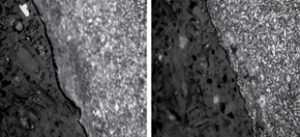
Figure shows two different positions of the hot pre-processing heat after the surface of the part is not processed. The heat after the organization is not abnormal, but there are more pits and gaps on the surface of the part. There is a black substance in the pit, which is initially considered an oxide.

Micro state of thermal front tooth surface cutting heat after processingFigure shows two surfaces of hot post-processing parts in different positions. The heat after the organization is not abnormal. There are slight pits and gaps on the surface of the parts. Following a successful cutting and peeling of the surface, the said pits and gaps are left on the surface of the matrix. In this case, there is no oxide in the pit.

Figure shows two different positions of forging heat after the part surface is not processed. The heat after the structure is not abnormal. There is no pit, notch on the surface of the part. The surface is relatively smooth with no abnormality.
On the whole, one of the biggest influences of the three different processes on the part is the surface state. Essentially, the main criterion for measuring the surface state is the surface roughness value. However, its role in the part fit process needs to be analyzed and verified by the friction coefficient as a variable.
The meshing contact surface of the P gear is subject to friction during the actual meshing process. In this case, the size of the friction force is different in terms of lubrication states. The mating tooth surface is analyzed numerically under the friction coefficient of 0.1, 0.3 and 0.5, respectively. This happens when the pressure of the tooth surface of the pawl is certain and the torque of the ratchet is fixed, based on the calculation of the three-dimensional transient dynamic mechanism model,
Table outlines a comparison of the results of the gear contact stress distribution under different friction coefficients.

Conclusion
P gear and parking tooth series products in the automotive transmission have an extremely important role, in the process of part design. In addition to considering its functionality, it is also important to consider its safety characteristics. Based on the special part shape of the gear, the process design and equipment selection in the processing process are particularly important.
A study is conducted on the load received during the use of the parts in this paper. The test results is analyzed. Starting from the static torsional test and durability test project, the influence of yield strength and contact fatigue strength on the surface notch crack source. In addition, it is considered integral to conduct a summary of the principle of the bending and machining process on the yield limit, contact fatigue strength, and impact strength of the tooth.
Among the elements involved include the holocularization refinement test of raw materials, the blank under different forging ratios, the tensile test of sampling in different directions, and the cutting deformation test of weak stiffness body clamping. Similarly, the heat treatment deformation test of thin-walled parts under different cutting amounts is also part of the major considerations. It is necessary to consider the microscopic surface morphology of forging and machined parts and the finite element analysis of contact stress under different surface roughness.
Here are the conclusions made:
(1) generation and encryption take place on the side of the parking tooth under a precise and appropriate forging ratio. New strengthening will also strengthen the bending strength along the fiber streamline. The improvement is relative to the parts directly machined by raw materials.
(2) The residual cutting stress will lead to uneven deformation of the part heat treatment and abnormal grain growth phenomenon. This is similar to the weak stiffness of the P gear in the machining clamping process generated by the force deformation. This could also be termed as processing under inappropriate cutting parameters. So, this has a certain impact on the accuracy of the part and product performance.
(3) The pre-thermal machining tooth surface and the thermal post-machining tooth surface are difficult to avoid the microscopic pits on the tooth surface. This is in comparison with the smoothness of the forged tooth surface. So, the machined surface is poor in microscopic performance. In other words, there are subtle pits, which may eventually evolve into cleavage crack sources.